Carrier Setup DL
This topic applies to downlink carrier configurations.
Save to 89600 Setup File
This feature saves the Carrier configuration as a 89600B VSA setup file, simplifying VSA configuration so you can quickly demodulate the signal. For information about setup file settings, refer to 89600 Setup File Setting.
Full-filled Config
Opens the Full-filled Configuration dialog window.
DL Test Model
Opens the Downlink Test Model dialog window.
DL FRC Configuration
Opens the Downlink FRC Configuration dialog window.
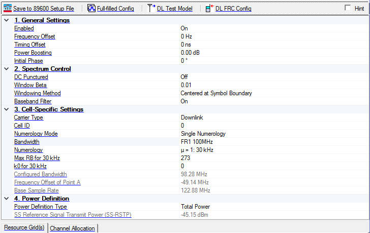
1. General Settings
Enabled
Choices: On | Off
Default: On
Enable or disable the carrier in waveform generation.
Displays the state of the carrier in waveform generation.
Frequency Offset
Range: -1 GHz to 1 GHz
Default: 0
Set the frequency offset to the carrier signal in Hz.
Timing Offset
Range: 0 to 0.01s
Default: 0
Set the timing offset of the carrier relative to others.
Power Boosting
Range: -40 to 40 dB
Default: 0 dB
Set the power boosting of the carrier relative to others.
Initial Phase
Range: 0 to 360
Default: 0
Enter the initial phase of the carrier signal in degree.
2. Spectrum Control
DC Punctured
Choices: On | Off
Default: Off
Set whether DC is punctured in the final signal for current carrier.
For uplink carrier with Transform Precoding enabled for UL-SCH, DC Punctured is forced to Off.
Window Beta
Range: 0 to 0.07
Default: 0
Set the windowing length used to smooth OFDM symbol transitions. Specify this value as a fraction of FFT Length, not the percentage. Using windowing can help reduce out-of-band energy and eliminate the spurs in adjacent channel. It is not applicable for PRACH carrier.
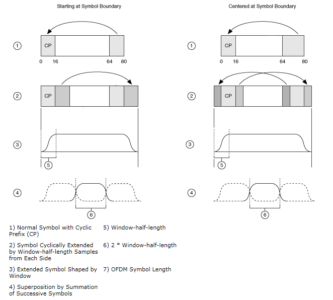
Windowing Method
Choices: Centered at Symbol Boundary | Starting at Symbol Boundary
Default: Centered at Symbol Boundary
Select the windowing method applied to the OFDM symbol transitions. The raised cosine window can be centered at the OFDM symbol boundary, or starting from the OFDM symbol boundary.  View image.
It is not applicable for PRACH carrier.
Centered at Symbol Boundary specifies that the window is applied with its center at the boundary between two orthogonal frequency division multiplexing (OFDM) symbols.
Starting at Symbol Boundary specifies that the window is applied with its starting position at the boundary between two OFDM symbols.
Baseband Filter
Choices: On | Off
Default: On
Enable or disable baseband filter. The filter is applied to each numerology of this carrier. It is a low-pass
Taps: 1024
Band margin: 1 RB for each side
3. Cell-Specific Settings
Carrier Type
Choices: Downlink | Uplink | PRACH | Continuous Wave
Default:
Select the carrier type. If you need to transmit all of them together in the same carrier, use multi-carrier with same frequency offset.
Displays the carrier type.
Cell ID
Range: 0 to 1007
Default: 0
Set the cell ID for the carrier.
Numerology Mode
Choices: Single Numerology | Multiple Numerologies
Default: Single Numerology
Select the numerology mode for the current carrier. For Single Numerology mode, a Numerology selection parameter appears (along with supporting parameters) in this property grid and all the BWPs/Channels use this numerology. For Multiple Numerologies mode, a Resource Grid(s) tab appears below, allowing you to enable the resource grid for each numerology, and the numerology for each BWPs/Channels is editable.
Displays the numerology mode for the current carrier. For Single Numerology mode, a Numerology selection parameter appears (along with supporting parameters) in this property grid and all the BWPs/Channels use this numerology.
Bandwidth
Choices: Based on the Table 5.3.2-1 and 5.3.2-2 in 38.104.
Default: FR1 100M
Select the Bandwidth configuration for the carrier.
Numerology
Choices: u = 0: 15 kHz | u = 1: 30 kHz | u = 2: 60 kHz Normal CP | u = 2: 60 kHz Extended CP for FR1; u = 2: 60 kHz Normal CP | u = 2: 60 kHz Extended CP | u = 3: 120 kHz | u = 4: 240 kHz for FR2.
Default: µ = 1: 30 kHz
Select the numerology for current carrier in Single Numerology mode.
Max RB for 15 kHz / 30 kHz / 60 kHz
Range: Related to the numerology.
Default: 273
Set the maximum number of RB for current numerology of the carrier in Single Numerology mode.
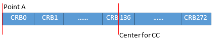
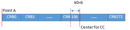
k0 for 15 kHz / 30 kHz / 60 kHz
Range: -6, 0, 6
Default: 0
Set the k0 for current numerology of the carrier in Single Numerology mode. It is used to adjust the center of carrier.
Frequency Offset of Point A
Display the relative location of Point A (in Hz) from the middle of carrier.
Configured Bandwidth
Display the occupied bandwidth of the carrier. It is calculated by the maximum bandwidth between each enabled numerology.
Base Sample Rate
Display the base sample rate of the carrier. It is a suitable sample rate for the current carrier.
4. Power Definition
Power Definition Type
Choices: Total Power | SS-RSTP
Default: Total Power
Select the power definition type. If Total Power is selected, the power reference is Amplitude of Instrument, and SS-RSTP is automatically calculated. If SS-RSTP is selected, power reference is the SSS symbol of first active SS Block, and Amplitude of Instrument is automatically calculated by SS-RSTP.
To set/get SS-RSTP, all the carriers should be downlink carrier with SS/PBCH enabled, otherwise the power definition type is fixed to Total Power and SS-RSTP is shown as N/A.
The SS-RSTP may not be correct if the waveform configuration is complicated.
The Power Boosting of Carrier is read-only and be automatically coupled when Power Definition Type is SS-RSTP.
SS Reference Signal Transmit Power (SS-RSTP)
Range: -200 dBm to 30 dBm
Default: -45.15 dBm
Set or get the resource element power of SSS symbol of the first active SS Block. If Power Definition Type is Total Power, SS-RSTP is automatically calculated by the Amplitude of Instrument. If Power Definition Type is SS-RSTP, the Amplitude of Instrument is automatically calculated by SS-RSTP.
If the calculated Amplitude of Instrument is out of the range, there will be an error.